Scanning of moulds or prototypes for analysing geometric deviations with respect to the cad model
If you need to analyse the deformations of a component or a mould with respect to the reference CAD model used in the design phase or simply need to verify a surface or profile shape tolerance present in a design, then what you need is the analysis of the deviations displayed in the form of a colour map. This technique allows the points detected using three-dimensional measurement systems to be superimposed on the CAD model and after appropriate alignment methods (Best-Fit, RPS, Geometric) to evaluate the deviations (distances) between what was detected and what was determined at the design stage.
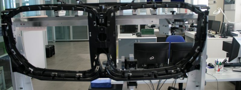
The analysis is suitable for complex geometries, such as moulds or free-form objects, commonly associated with the automotive, household appliance, or industrial design sectors in general. Some examples of parts analysed in such a way are lenses and headlight bodies, air ducts, bodywork parts, aluminium or plastic components in three dimensions, structural mechanical components (housings, covers, timing cases or gearboxes) typically manufactured by moulding plastic and die-cast aluminium.
Deformations are displayed using a colour map of the deviations detected between the 3D STL file (acquired using the scanner) and the reference CAD model. The STL file thus created can be supplied to the client upon request to enable them to perform a precise analysis of the deformations so they can correct the mould to adjust for any deformations identified on the piece produced. This activity can be carried out both at our laboratory and on-site at our client’s premises.


